
For superstructure replacement projects, rehabilitating the existing substructure instead of replacing the bridge itself is often a great challenge. However, with the reduced transportation funding pushing many DOTs to preservation mode rather than complete replacement, rehabilitation of structures is needed to keep the traffic moving safely on new and existing structures.
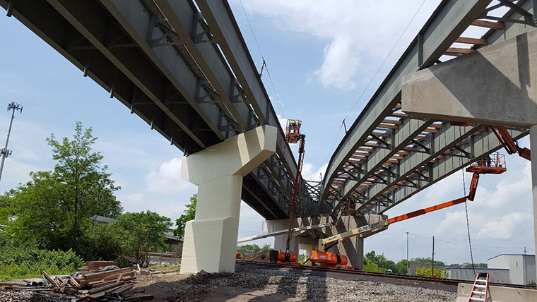
While rehabilitating four interstate ramps in Dayton, Ohio, for the Ohio Department of Transportation, District 7, we discovered that replacing the superstructure on MOT-35-1516N, a 12-span, curved ramp over CSX and Norfolk Southern Railroads with no hinges, would add too much stress to the existing substructure to meet Association of State Highway and Transportation Officials (AASHTO) Standard Specifications. By using an innovative approach to rehabilitate the substructure, we ultimately saved the owners over $2 million. Throughout this project and many others, our team has learned many valuable lessons that have aided us in providing effective solutions. Here I provide a case study to help you determine if rehabilitating your substructure is a viable alternative for your bridge project.
Replacing the existing superstructure
The Y-geometry of the ramps, locations of the drop beams, and the ramp closure restriction all factored into the decision to replace the superstructure on MOT-35-1516N. This also allowed us to improve the joint condition by relocating them to the piers. Due to how much the loading and geometry of the piers would change, we evaluated the substructure capacity for the proposed loading, including thermal forces due to elastomeric bearings and an additional beam line for unit 3 for maintenance of traffic.
Analyzing the existing cap and column and T-type Piers
Using analysis software, we reviewed the impacts the superstructure replacement would have on the substructure. Most components of the cap and column piers (Piers 8, 9, 10 & 11) would remain unaffected, but several key areas on the cap and column piers would be impacted.
- The pier cap shear capacity would be 33-46% over.
- The bearing capacity on piers 8 and 11 would be 5% over.
For the T-type piers (Piers 2-6, 7N, 7S, 12, 13), the pier cap shear and moment capacities were adequate. Majority of stem and some footing of T-type piers would be impacted.
- The pier stem moment capacity would be 25-150% over.
- The flexural capacity of footing for pier 7N would be 90% over and piers 7S would be 36% over.
- Maximum overstress on the bearing capacity of T-type pier footings would be less than 10%.
We either needed to fully replace the bridge or come up with an innovative approach to rehabilitating the substructure. To minimize schedule and cost impacts, rehabilitation of overstressed substructure components was chosen in lieu of substructure replacement.
Rehabilitating the cap and column pier caps and T-type piers
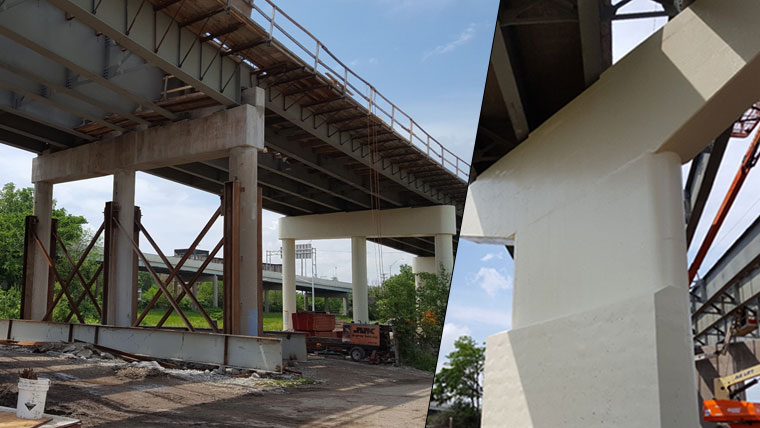
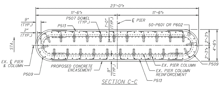
Our team explored multiple options to improve the shear capacity on the cap and column pier caps. These included fiber wrapping the pier caps or designing a concrete encasement for them. We ultimately decided on concrete encasement as this increased the shear capacity through composite action and would make inspection easier, compared to fiber wrapping them.
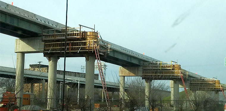
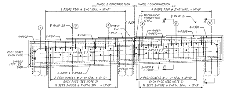
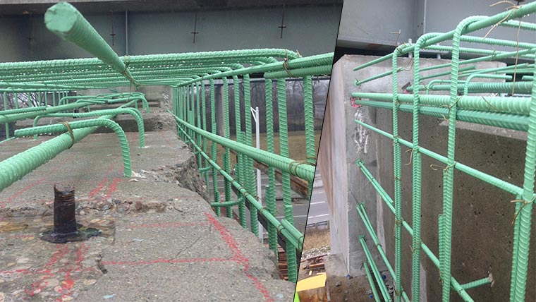
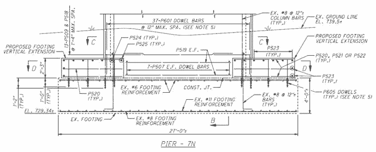
Concrete encasement with vertical reinforcing steel was also used to improve the T-type pier stem wall’s flexural capacity. The vertical reinforcing steel was doweled into the footing to develop the flexural reinforcement.
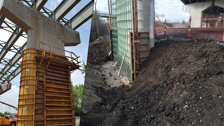
Concrete topping with vertical steel dowels to develop composite action with the existing footing was used to improve the flexural capacity of overstressed T-type pier footings.
Coordination and stakeholder involvement
There were multiple factors that required coordination with various stakeholders to complete the project successfully. In addition to limiting the project construction costs, the goal was to construct the project per the original schedule with minimal disruption to travelers. We developed a complex Maintenance of Traffic Alternatives Analysis to stage construction alongside other ongoing projects in the area to limit impacts to the public.
Since MOT-35-1516N bridge ran over two railroads, their involvement both early on and throughout the process was paramount. Through our team’s extensive experience designing structures over railroads, we have gained valuable lessons that can be widely applied. When designing structures over railroads, some critical considerations include:
- CSX & NS require flaggers within 30 feet of the tracks so consider working within 25 feet.
- When excavating near a railroad, it is good to provide a cross section with sheeting/open cut limits detailed.
- Consider placement of equipment and thickness of shoring in your design.
- It is highly risky to assume existing foundation limits were built precisely per the plans.
- Reconfirm railroad concurrence prior to selling the project and again at pre-construction.
In the end, our team was able to meet ODOT’s goals of delivering a quality, cost-effective, practical and safe project that their travelers will enjoy for years to come.