
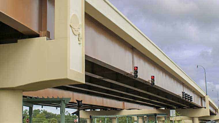
Steel plate girder bridges are a suitable bridge option that support a variety of roadway structures, including railroads and highways traffic, so it’s no surprise that they have been one of the most commonly used bridge types since the late 19th century. Steel plate girder bridges are generally used in the 100 foot to 400 foot span range. Steel plate girders consist of top and bottom flange plates welded to thinner web plates with fillet welds. The web plates will be either stiffened or un-stiffened.
The process of detailed design and plan preparation of steel plate girder bridges using AASHTO Load and Resistance Factor Design (LRFD) specifications is quite involved. In addition to the LRFD specifications, intuition, judgment, and previous experience have to be used to obtain an economical practical design in an efficient manner. I and my peer engineers have extensive experience from numerous steel plate girder bridge designs. Based on this wealth of experience, I have compiled the top five practical guidelines to consider in your designs for steel plate girder bridges per AASHTO LRFD specifications.
In addition to the guidelines provided here, the information provided in the AISC Standard Plans for Steel Bridges for 1 to 4 Span per AASHTO LRFD 10th Edition can be used as a starting point.

1. Web depth and thickness
The most important parameter for the design of steel plate girder bridges is the selection of near practical optimum web depth. As a first step, generally the minimum steel plate girder depth can be determined based on span-to-depth ratios in AASHTO Table 2.5.2.6.3-1 for tangent girders or Equation 2.5.2.6.3-1 for curved girders. Based on principles of engineering mechanics, it may seem reasonable to select the deeper web depths. However, in most of the projects, the structure depth will be restricted by minimum vertical clearance or hydraulic requirements. In addition, increasing web depth may require thicker webs to satisfy the AASHTO requirement D/tw < 150 for girders with no longitudinal stiffeners.
Another side effect of using deeper girders is the increased height of backwall or integral abutments resulting in longer wingwall lengths and associated increased substructure cost. The practical optimum depth will in general be 5% to 15% more than the minimum depth required. Specifying web depth in 3-inch increments and considering multiple web depths within the range of 1.05-1.15 x minimum web depth will in general lead to near optimum depth. For example, for a 140-foot span length (L) simple span steel plate girder bridge, the minimum steel plate girder depth = 0.033 x L = 0.033 x 140 x 12 = 55.44 inches, and overall minimum depth of composite I- girder = 0.04 x L = 0.04 x 140 x 12 = 67.2 inches. Assuming an 8.5-inch composite deck and 2-inch haunch, the minimum steel plate girder depth will be = 67.2 inches – 10.5 inches = 56.7 inches; assuming a minimum top flange of 1 inch and a bottom flange of 1 ½ inches, the minimum web depth will be close to 53 inches. Therefore, for a 140-foot span steel plate girder, 56-inch, 57-inch, and 58-inch web depths (which are in the range of 1.05-1.10 x minimum web depth) can be investigated for the preliminary design to determine near optimal structure depth. For a 140-foot single span plate girder bridge, the AISC Standard Plans for Steel Bridges provides a web depth of 54” for 8-foot girder spacing and 55” for 10-foot girder spacing and 56” for 12-foot and 14-foot girder spacings.
If the 140-foot span length (L) is the longest span of any continuous span plate girder bridge, the minimum steel plate girder depth = 0.027 x L = 0.027 x 140 x 12 = 45.36 inches, and the overall minimum depth of composite I- girder = 0.032 x L = 0.032 x 140 x 12 = 53.76 inches. Assuming a minimum top flange of 7/8 inch and a bottom flange of 1 inch, the minimum web depth will be close to 43.5 inches. Therefore, for a 140-foot maximum span continuous steel plate girder, 46-inch, 47-inch, and 48-inch deep web depths (which again are in the range of 1.05-1.10 x minimum web depth) can be investigated for the preliminary design to determine near optimal structure depth. Similarly for a three span steel plate girder bridge with 117-foot end spans and 150-foot mid-span, 49-inch, 50-inch and 51-inch web depth can be investigated for the preliminary design and matches with the 50-inch web depth provided in the Continuous Span Standard Solutions by NSBA for the same span configuration.
As mentioned before, if the structure depth is restricted by minimum vertical clearance or hydraulic requirements, then a web depth of 54 inches for a 140-foot simple span, and 43.5 inches (an exception to the 3-inch increment rule for depth of a constrained bridge) for a 140-foot maximum span continuous span bridge can be utilized. To avoid excessive fabrication costs, uniform web depths should be utilized. However, for long span bridges (meaning spans in excess of 250 feet), if there is great variation between the smallest and longest span, a tapered web depth can be utilized to achieve economy in girder design. In addition to the AASHTO D/tw requirement, minimum web thickness should satisfy absolute minimum web depth per design agency requirements. For example, South Carolina Department of Transportation’s (SCDOT) minimum web thickness is ½ inch, which will control the web thickness required for web depth up to 75 inches. It is generally a good practice to select a thickness close to D/tw = 120-130 to reduce the number of transverse stiffeners and design a partially stiffened web.
2. Number of girders and deck overhang
For an economical superstructure design, the number of girders should be minimized. Reducing the number of girders will lead to other cost savings associated with intermediate diaphragms, bearings, and girder erection. For a given width of a bridge, the number of girders will be determined based on the design agency’s (and/or state DOT’s) requirements regarding the minimum number of girders, maximum allowable girder spacing, and maximum allowable deck overhang. In general, the minimum number of girders will be four. However, for a narrow bridge in a remote location and very low average daily traffic (ADT), three girders can be used if the design agency permits. If three or fewer girders are used for smaller width bridge or in any phase of part-width bridge construction project, during deck pour, the girders shall be checked for Elastic Global Lateral Torsional Bucking per Section 6.10.3.4.2 of AASHTO LRFD Specifications, 10th Edition.
The most common spacing for plate girders ranges from 9 feet to 11 feet. Some design agencies have a maximum limit on the girder spacing—South Carolina Department of Transportation (SCDOT)’s is 10 feet, 6 inches. For decks designed using a traditional deck design method, costs associated with increased deck thickness and/or reinforcement should be considered for wider girder spacings. Once you have established the number of girders, the girder spacing and deck overhang should be determined so that the performance ratio for both the exterior and interior girders are close (within 5% to 10%). For girders designed using AASHTO LRFD specifications, the deck overhang should be kept close to 3 feet, 0 inches to maintain a balanced design. If the deck overhang is close to the maximum limit, then the girder design will be most likely controlled by the exterior girders, and the interior girders will not be fully utilized.

3. Steel grades and homogeneous vs. hybrid design
If the project location and agency policy allow the use of weathering steel, unpainted weathering steel Grade 50W (50 ksi steel) or HPS 70W (70 ksi steel) should be the first choice. Painted steel increases initial and life cycle costs. For spans less than 140-150 feet, homogeneous design utilizing 50 ksi steel for both flanges and web elements of the plate girder generally provides an economical design. For spans in excess of 150 feet, hybrid design utilizing 50 ksi for web plates and top flange plates in the positive moment region, and 70 ksi steel for the entire bottom flange plates and top flange plates in the negative moment region provides an economical design. Continuous Span Standard Solutions by NSBA provides preliminary design for both homogeneous and hybrid design for two span (100-250 FT), three span (150-300 FT) and four span (150-300 FT) continuous plate girder bridges.
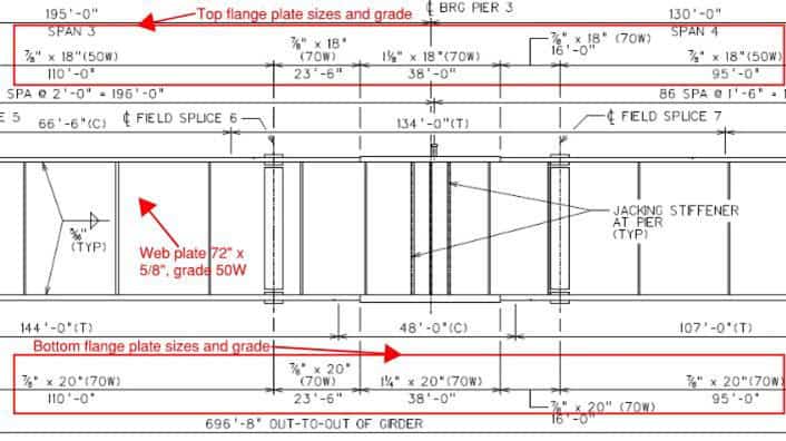
4. Flange width and thickness
The minimum flange width is 12 inches, or 14 inches as specified by design agencies, and is usually sized in 2-inch increments. Compression and tension flanges should be sized to satisfy AASHTO 6.10.2.2: bf/(2tf) <= 12.0, bf >= D/6 and tf > 1.1 tw. For economical composite plate girder design, the width of top flanges is normally smaller than the width of bottom flanges. For satisfying stress checks during deck pour and to alleviate out-of-plane distortions during shipping and handling, the width of top flanges in compression should be greater than or equal to the length of the girder shipping piece (inches) / 85.
As an example, for the 140-foot simple span with 60-inch deep x ½-inch thick web, and with a 90-foot shipping piece for the top flange, the minimum top flange width = 90×12 / 85 = 12.7 inches, say 14 inches. For long span girders with a maximum shipping piece of 125 feet, the minimum width of top flanges in compression = 125×12 / 85 = 17.64 inches, say 18 inches. Minimum flange thickness is ¾ inch or 7/8 inch as specified by design agencies, and should also satisfy the requirement of >= 24/bf. For a given plate girder depth, the flange width and thickness are increased so that the performance ratio is <= 1 or 0.95 for both positive and negative moment regions as desired by the designer based on the level and stage of design. The performance ratio/load rating should be evaluated for both strength and serviceability requirements for various stages of construction and final condition. For locations away from interior bents, the size of both top and bottom flanges can be reduced by using thickness transition in flange plates between field splices. The cost of using a filled weld for plate transition should be compared with the cost of using flange plates of uniform thickness between field splices as per the design agency guidelines to achieve economical flange plate transitions. To increase economy, at field splices away from the piers, both the width and thickness can be reduced to achieve target performance ratio matching interior supports.
5. Intermediate diaphragm
Intermediate diaphragms may be X-type or K-type. X-type cross frames are generally used when the ratio of girder spacing to the girder depth is less than 1.5. For K-type intermediate diaphragms, the diagonals will be connected to the middle of bottom strut. The cross-frames for tangent girders are usually spaced 20 feet to 30 feet in the positive moment region, and a closer spacing of 15 feet to 20 feet in the negative moment region. They also need to satisfy design agency requirements such as ODOT’s requirement of a 25-foot maximum in the positive moment region and a 15-foot maximum in the negative moment region. If cross frames near the interior supports are spaced less than 3D (D= depth of web), then cross-frame connection plates can be used as stiffener plates, eliminating the need for transverse stiffeners near interior supports.
While the process of preparing detailed design and plans for steel plate girder bridges using AASHTO LRFD specifications can be complex, it can absolutely be accomplished successfully by experienced engineers. Recently, I and my peers at Mead & Hunt completed multiple steel plate girder bridge projects, such as the Backgate Bridge in South Carolina and the Hartland Bridge in West Virginia, that were very successful and resulted in significant cost savings for the client. As stated previously, the project not only required extensive knowledge of AASHTO LRFD specifications, but significant experience, judgement, and intuition as well.